Brunel Swivel Bridge Project Plans
During our investigation, we have looked at original plans, plans of modifications and created plans to describe what we have found, to fortell what we may find and will all aid what will need to be done. This will help with funding applications, increase public understanding, and get help.Original drawings
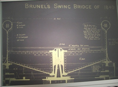
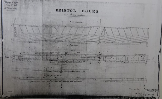 Brunel Swivel Bridge Drawing 1849 |
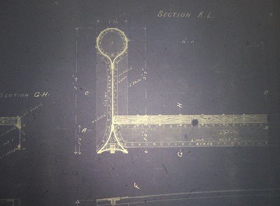 Tear drop cross section |
 Pintle section modified in 1902 |
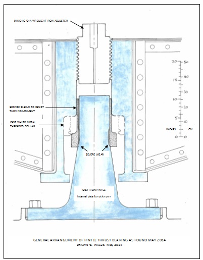
Geoff Wallis's plan of the pintle |
Bob Watkins, one of our volunteers has been producing amazing CAD drawings of all the parts of the Bridge and predicted that there would be large timber beams just under the ground, supporting the turn-table wheels. Mike B, Josh and Bob dug down to see if they existed, and sure enough discovered a 12 inch square baulk to everyone's delight.
Bob in action
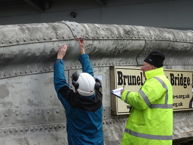
Martyn measuring and Bob taking notes |
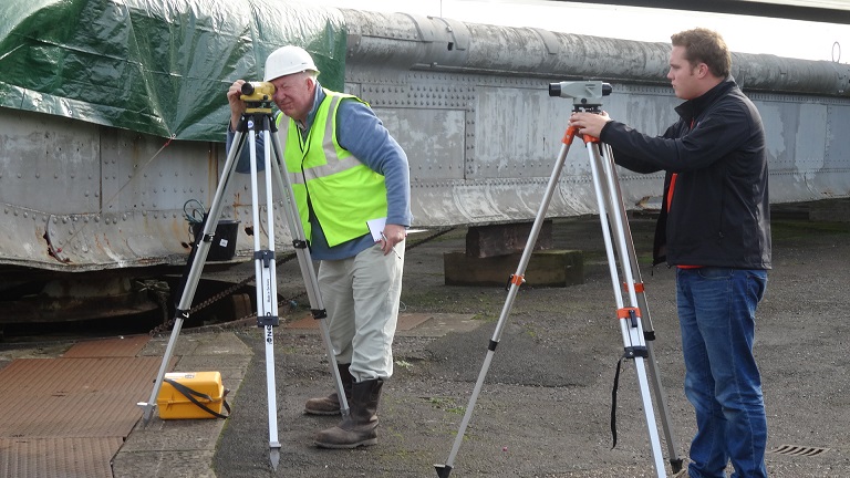
Bob with graduate engineers |
Drawings -Table of contents
Inspection notes
Part of the level survey that we carried out on the area close to the bridge. The interest relates to two items:
- The turntable base to the bridge;
- The rail track for the rear wheels.
Turntable base The turntable base comprises two large iron castings; a small segment immediately above the masonry lock wall; and a larger segment farther away from the lock wall. The two segments are bolted together. For the turntable base, we took levels at a series of 12 locations around the turntable on the top of the outer upstand to the base plate. As you will see (and as you can easily see on site), the levels are all slightly higher than the surrounding ground level and the levels along the lock wall. In fact, the turntable is about (on average) 240mm above the levels along the top of the front face of the lock wall. The variation in the levels around the top of the turntable base is about 36mm, with high points approximately where the two segments are bolted together and low points to the south of the bridge. The variation of 36mm in levels around the turntable base is larger than expected on the basis of manufacturing and workmanship tolerances, but there does not appear to be any significant predominant tilt in the base plate which might be indicative of differential settlement due to local foundation failure.
We also took levels on the base plates which support the four rotor wheel housings within the base. The variation in the levels on the four plates is only 6mm. (The plates are, on average, 487mm below the top of the outer upstand). This suggests that the variation in the turntable base plate levels pre-date the setting of the wheels, which I presume was carried out prior to circa 1967.
Although, the full load of the bridge whilst moving will not have been placed on the rotor wheels since circa 1967, it is likely that a substantial portion of the full load will have been placed on the wheels in its stationary position. Other things being equal, one might expect to see variations in levels on the base plates to the wheels if foundation movement had taken place in the intervening period. The levels on the base plates is thus encouraging, although not conclusive.
Rail track for the rear wheels The rail track is set approximately level with the surrounding surface except at the location of the hydraulic valve pit where the track has been covered with tarmac, presumably because the top of the valve pit was proud of the surrounding surface and presented a trip hazard. We took levels along the rail track. There is a variation in levels of about 38mm. The majority of this variation occurs over the section near the rear of the bridge where the track runs ‘downhill’ to match the surface levels along the lock wall. The track will obviously need to be cleared of the tarmac locally, but I would suggest that the entire track also needs to be re-levelled eventually so that loads in the hydraulic machinery during operation do not fluctuate unduly. Should this provide a ‘downhill’ section from each end to allow the bridge to accelerate and decelerate from start to stop? Sounds like I need a mechanical engineer!
North Abutment The only thing to note here is that the level on the north abutment is higher than at the south abutment by about 380mm. Bob has no reason to suppose that this is in error because quay levels on both sides of the lock are similar to each other and the levels that we have obtained appear to tie in with the results of the earlier (but recent) survey plan which we think was produced by Bristol Docks Engineer. This must mean that the abutments were originally built to different levels. Based on the existing topography, there appears to be no reason why the levels should be different, but the 1873 drawing for the north abutment indicates a level difference from lockside to abutment of about 45ins (1.143m) which corresponds well with the difference in level found in our survey of about 1.128m. Also, a transition slope on the planking to the bridge as it transfers to the north abutment appears to be shown on the earlier drawings. Any thoughts for the reasons why??
Ground Investigations
January 2016: Investigation of the ground around the Swivel Bridge, including a cable percussion borehole, one day's trial pitting at three (or possibly four locations if time permits) up to 3.5m mbgl, with insitu geotechnical sampling, all supervised by an engineering geologist, and an archaeologist.
The proposed locations of the single borehole and trial pits are shown on the plans.
Geocon Site Investigations Ltd of Almondsbury is the chosen contractor, and have been made aware of the Plimsoll Swing Bridge and the need to take down the drilling rig before bridge swings.
particular hazards which have already been identified:
- the presence of the public in the vicinity;
- the unprotected edge of the Entrance Lock to the north of the bridge;
- the 3T vehicle-weight limit from Brunel Lock Road to the bridge site;
- the risk of flooding at extreme high tides;
- risk of bridge movement and distress if the ground adjacent to timber blocks, on which the bridge is presently supported, is disturbed;
- the low headroom under the Plimsoll Swingbridge when it swings over the whole site potentially one hour before to three hours after high tide twice per day.
Turntable base and foundations
Bob Watkins predicted that there would be large timber beams just under the ground, supporting the turn-table wheels.
Mike B, Josh and Bob dug down in August 2014 to see if they existed, and sure enough discovered a 12 inch square baulk to everyone's delight. Hammering a screwdriver into it revealed that most of the timber was sound, although damp, and it smelled strongly of tar, so presumably had been treated when installed.